Page 1
ECOA INTRODUCTION
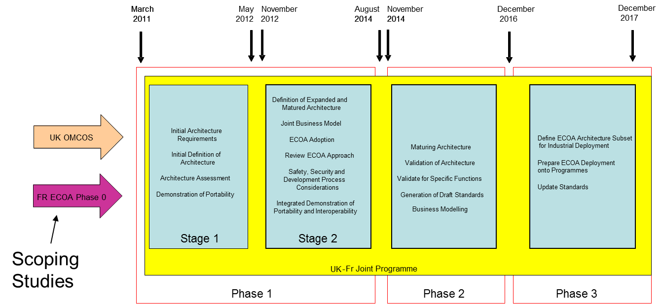
The governments of the United Kingdom and France established the ECOA programme in March 2011 with the primary objective of developing and demonstrating a comprehensive next generation software architecture specification. The primary focus for this architecture is combat air mission systems for unmanned air systems and fast jet applications although it is envisaged that it will be relevant to other domains.
The primary aim of the programme is to develop an architecture specification that is an enabler to the following core objectives:
- Risk reduction in the integration of increasingly complex mission systems
- Reduce development and through life-costs of future collaborative development programmes
- Reduce development timescales and improve affordability through a business model of software reuse
- Improve competition through broadening the software supplier base
- Foster innovation through non-traditional suppliers
- Create a structured market for avionics applications
- Enable the development of complex, networked systems to deliver future customer capability requirements
ECOA OBJECTIVES
The ECOA programme is one of a number of integrated initiatives, driven by the UK and French customers, to deliver a step change in mission systems software affordability through increased reuse of applications between platform programmes. ECOA aims to reduce development, through-life costs and timescales for new collaborative development programmes by reducing risk in the integration of complex mission systems, promoting software reuse and improving competition in the software supplier base.
ECOA has been developed for avionic mission systems software in its widest sense but it is anticipated that the concepts and standards of ECOA would apply equally well in the land and sea domains, and in contexts where mission capability spans all three.
This aim requires a scalable underlying architecture, from individual hardware components to network level interaction, incorporating standard interfaces. In some cases ad-hoc connectivity and distribution over multiple platforms supported by discovery, cooperation and interaction may be required. The architecture will also be required to support real-time service expectations of system components.
ECOA OBJECTIVES
An aim of ECOA is to support implementation of the majority of the non-safety-critical (including real time) software of a mission system with open, agreed interfaces; the longer term aspiration is to support more critical and mixed integrity software. As far as managing more critical software is concerned, ECOA supports this by defining a High Integrity Ada language binding. An ECOA implementation must be capable of interacting with legacy / system specific areas that may not be hosted on the ECOA architecture.
For more information please refer to the Official ECOA Website
ECOA PROGRAMME
The ECOA programme builds on United Kingdom and French avionics architecture research programmes that originated in the early 1990s. These earlier research programmes focussed on a number of interest areas, in particular, modular avionics. ECOA is complimentary to previous programmes and is primarily focussed at the application layer. It can be deployed on the modular avionics architectures that have been previously developed, further enhancing the overall capability in this area.
Prior to the formation of the United Kingdom and French ECOA collaboration in March 2011 both nations performed scoping studies. In the United Kingdom this was completed as part of the OMCOS programme and in France the ECOA Phase 0 programme.
ECOA FUTURE STRATEGY
ECOA FUTURE STRATEGY
ECOA FUTURE STRATEGY
ECOA INTRODUCTION - KEY CONCEPTS
ECOA seeks to exploit architectural concepts and systems engineering techniques that are already widespread in other industry sectors in the development of complex information systems. These include:
- Component-based software engineering;
- Loosely-coupled, service-oriented architectures;
- Model-driven engineering and model-driven development;
- Publisher-subscriber data-oriented architectures.
These approaches offer increased flexibility, but ECOA also recognizes the need for rigorous qualification and certification in the target avionics software environment. ECOA must also support:
- Deployment of ECOA technology on a variety of hardware and software platforms;
- Integration of ECOA applications with non-ECOA applications.
APPLICATION SOFTWARE COMPONENTS AND SERVICES
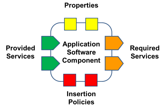
In an ECOA System, an Application Software Component (ASC) embodies some element of system functionality, and will have well-specified behaviour (functional, temporal etc.) which may be tailored through Component Properties. Insertion Policies that accompany an ASC definition express those necessary characteristics of any platform that is to host an instance of such a Component.
The architecture of an ECOA based system is defined from a Component and Service Oriented Architecture (SOA) perspective. A system's architecture is assembled by linking Components together according to SOA principles:
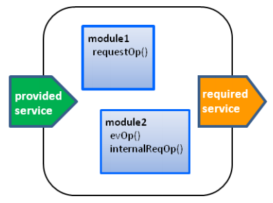
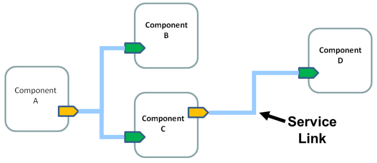 An Assembly Schema comprises the set of declarative artefacts that are created during this design process. The figure shows a diagrammatic
representation of an Assembly Schema for a simple system comprising four Components and three Service Links.
An Assembly Schema comprises the set of declarative artefacts that are created during this design process. The figure shows a diagrammatic
representation of an Assembly Schema for a simple system comprising four Components and three Service Links.
INVERSION OF CONTROL
In ECOA it is the infrastructure code that controls the execution of the system specific code, provided by the Module Operations in response to the actions of other Modules. This is an Inversion of Control (IoC) with respect to traditional procedural programming in which application code commonly calls into the operating system / middleware to perform task scheduling activities. The benefits of IoC are that it helps:
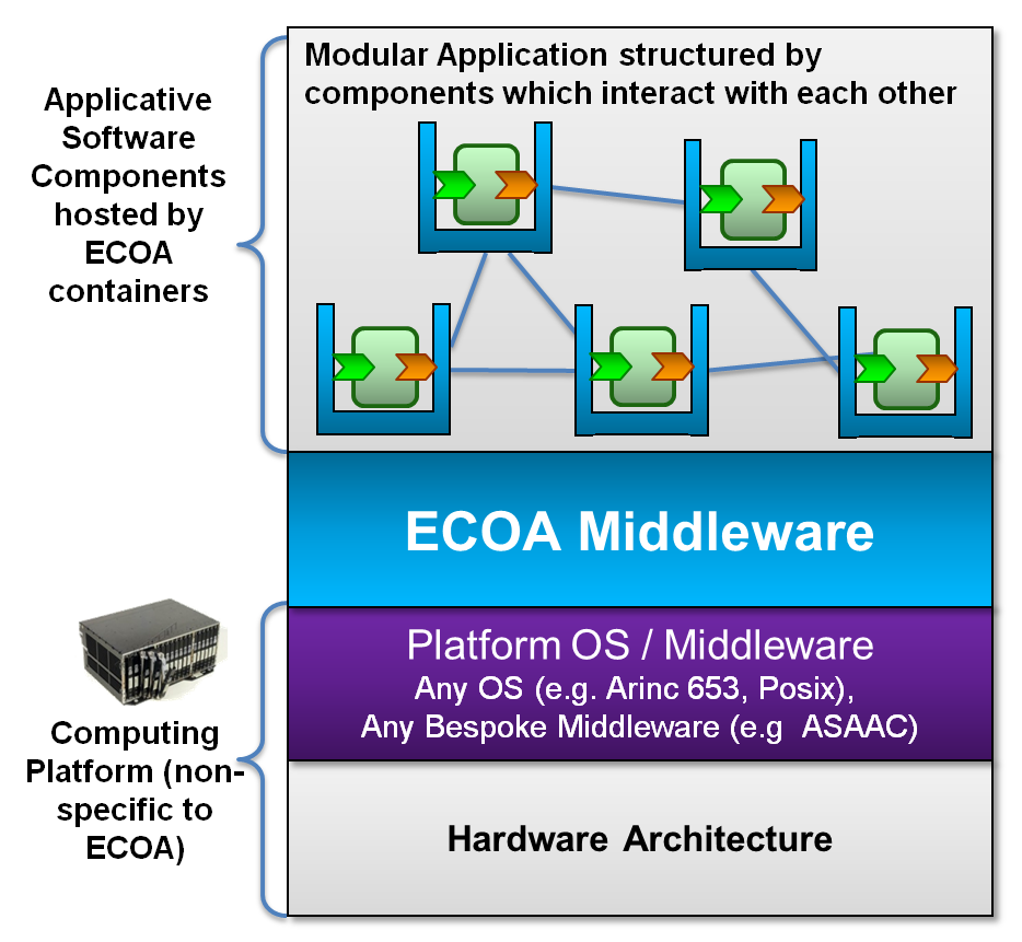
An implementation of Infrastructure code is called an ECOA Software Platform. It encompasses the Platform Integration Code, the computing facilities provided by the underlying operating system or middleware, as well as the means to interconnect with other ECOA Software Platforms.
An ECOA Software Platform provides Containers within its Platform Integration Code. A Container is designed for one or more Application Software Component (ASC) implementations that it hosts. The Container and ASC are constrained to interact via their respective interfaces, which represent a set of custom, narrowed APIs designed to expose the minimum 'surface area' between an ASC and the ECOA Software Platform.
SOFTWARE MODULES
Software re-use is a motivating principle of ECOA. The concepts described up to this point support re-use at the Component and Service level. A Module embodies some functionality of a Component and ECOA seeks to impose minimal constraints on how its behaviour is implemented. Modules are the unit of deployment in ECOA. A declarative entity in the ECOA XML Meta-model called a Module Type provides the contract for implementing a Module, in terms of both the Module Operations it must implement and those that it depends upon. Different Module Implementations may exist: perhaps targeting different hardware; perhaps written in different languages; but compliant with the same Module Type contract.
Module developers can conceivably use any technology, languages, libraries etc. to support implementation. However, to guarantee portability
and reusability a Module should operate by using only the facilities provided by the Container that surrounds it.
The precise specification for transformation of XML declarations to code means that portable Module Implementations can be developed: - Cross-compiled
object code may be delivered to system integrators who can compose Modules from different suppliers together to form their systems, without the need to
share source code or header files.
Module Implementations should be re-entrant. Modules are instantiated by the ECOA Software Platform, and can expect the platform to call into the Entry Points that implement Module Operations. A Container-provided thread is used for all interaction at a Module Instance's boundary with the ECOA Infrastructure: one thread per Module Instance. In addition optional User Context and Warm Start Context can be maintained by the platform, ensuring functional data values are retained between operation invocations, or in the case of a re-start.
MODULE AND CONTAINER INTERFACES
The Container concept and the custom, narrowed Application Program Interface (API) through which Containers and Components must interact are key ECOA principles. The API is realised at the ECOA Module level with the Container-facing aspect of a Module being termed the Module Interface and the Module-facing aspect of a Container termed the Container Interface.
The Module Interface is derived from the Module Type. Module Interface entry points are handlers for Module Operation invocations coming via the Container from the wider ECOA System. Methods exposed by the Container Interface provide the means by which Modules can call Module Operations on other Modules or Components, or make use of Infrastructure services. A Container Interface implementation may be mechanistically derived (code generated) in its entirety from the Module Type, Module Implementation and Module Instance and supporting declarations.
Infrastructure facilities provided by the Container Interface include time services, logging and fault management.
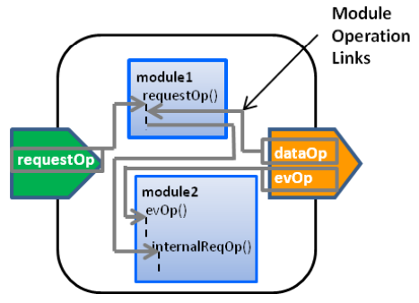
MODULE OPERATION LINKS
The realisation of an Application Software Component (ASC) Implementation from Module Implementations has been introduced. An ASC Implementation may comprise many Module Instances, perhaps with multiple instances for a given Module Type. Such Module Instances must be identified and connected together appropriately in order to fully elaborate the ASC Implementation. Module Operation Links, depicted in figure below, define the connectivity among the Module Operations of a Component's Module Instances in addition to specifying which Module Operations are to fulfil an ASC Implementation's Services.
CONTROL OF SYSTEM FUNCTIONALITY
Given the general Inversion of Control (IoC) principal that Module Operations are entirely passive, the question arises as to how the developer should create active Application Software Components (ASCs). A special pseudo Module called a Trigger Instance provides a mechanism to allow this.
Services are aggregations of Module Operations, just as ASC Implementations are aggregations of Module Instances. A Trigger Instance is specified in XML and wired to other Modules like any Module Instance, but its implementation is provided by the Infrastructure. Using a Trigger Instance an ASC developer can implement periodic activation at an operation level without reference to the underlying operating system / middleware, and without the need to depend on activation from an incoming Request or Event from an external Module.
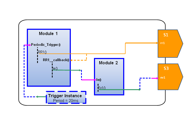
This figure depicts the Modules Instances and Module Operation Links within a Component which provides no Services and is not stimulated by any external calls. It contains two functional Modules and a Trigger Instance which is responsible for triggering execution of the Component on a periodic basis.
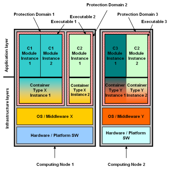
LOGICAL SYSTEM DEFINITION
ECOA defines the concept of a Logical System which is a logical definition of a computing infrastructure in terms of Computing Nodes, Protection Domains and Logical Links. Protection Domains allow for spatial, and possibly, temporal isolation or partitioning in order to, for example, support multiple safety or security levels. Logical Links are a simple abstraction of communication connections (e.g. VME or Ethernet) and are characterised by attributes such as bandwidth and latency.
Computing Nodes and Logical Links are characterised by simple attributes to enable modelling and assessment of a system prior to the completion of development. The definition of a Computing Node is deliberately abstract and may be a single core of a multi-core processor, a single core processor or a multi-core processor.
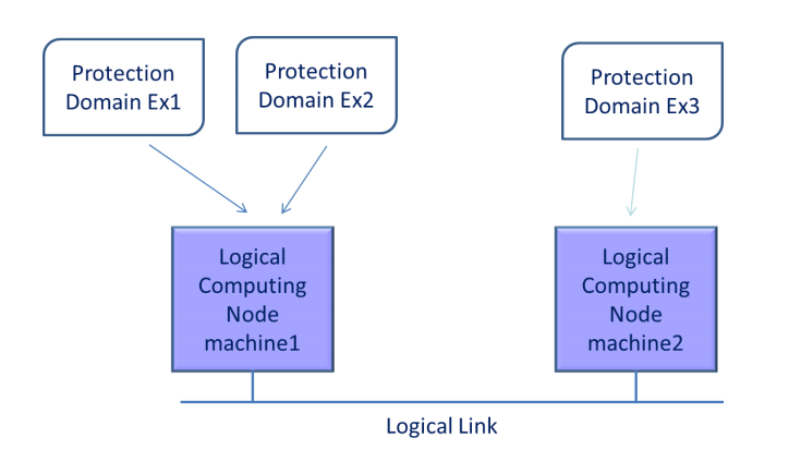
An example of a Logical System is shown in the figure opposite. It depicts machine1 connected to machine2 by a Logical Link. On machine1 there are 2 Protection Domains and on machine2 there is only one. On machine1 there must be a segregation mechanism at operating system level; whereas machine2 does not require this because it is only executing a single Protection Domain.
INTEROPERABILITY PROTOCOL
Communications between Computing Nodes, and between the Container Instances that they host, is achieved through the use of the ECOA Logical Interface (ELI). This interface is a standard, well defined protocol that is independent of the underlying physical transport media. Use of the ELI ensures that independently developed ECOA Systems or ECOA Stacks are able to make use of each-other's Services.
Service Definitions are composed 3 types of Service Operations:
All ECOA types exist within namespaces that can be nested. The following data type declarations are supported:
ECOA ARCHITECTURE SPECIFICATION
Traditionally platform-level software-intensive systems for military aircraft have been developed both "topdown", to meet a set of user requirements, and "bottom-up", to incorporate modified off-the-shelf subsystems with pre-conceived functionality and interfaces. As a result of this approach the interactions between subsystems and the host system are commonly not solely defined by the fundamental abstract function(s) of the subsystem in question.
- Subsystems may include functionality unrelated to their prime purpose which ideally belongs elsewhere, but included for convenience at design time.
- Subsystems may replicate functionality explicitly performed elsewhere to simplify a design-time negotiation, causing potential ambiguity in system data.
- They may include adaptations to cope with the peculiarities of subsystem interfaces - especially relating to timing and the frame to frame coherence of related data items.
- They may include local work-arounds and compensations for the subtle details of sub-system or host system behaviour.
This has resulted in platform-level systems with a number of undesirable properties:
- Their characteristics can be obscure, and are often understood only by a small number of experts who have gained knowledge of the idiosyncrasies of the system through experience.
- They are brittle. That is small changes, which may be inevitable for reasons of evolving requirements or obsolescence, can result in significant fracturing of the system and disproportionate difficulties and expense to repair it.
ECOA ARCHITECTURE SPECIFICATION
The modular, service-oriented, open architecture approaches of modern information and communications technologies have been shown to produce robust solutions which are capable of rapid integration and expansion.
There is an increasing need for more adaptable and affordable military avionics systems and the ECOA programme aims to address that need.
ECOA is developing the architectural principles, specifications and supporting infrastructure which will allow the functionality of avionic systems to be realised from a set of subsystems, designed to offer access to their fundamental capabilities, through clearly defined service calls. This will promote modularity, ease of integration, re-use and adaptability, each of which will improve the affordability of future military avionic systems.
ECOA ARCHITECTURE - OPEN STANDARD APPROACH
To achieve the ECOA programme goals it is necessary for the development community to work together using common standards. This standard must support the integration and re-use of existing products (including Commercial-Off-The-Shelf (COTS) software) alongside the integration of newly developed products.
This drives the need for published standards defining a common exchange format and standard interfaces
that can be used to develop modular architecture components. These components can be exchanged and re-used by the
relevant community. The ECOA Architecture Specification has been released for public consultation through the following national standard agencies:
The UK MOD DEFSTAN standardization body published Defence Standard 00-973.

The French BNAE standardization body published RG.Aero 000 973. It is fully interoperable with the DSTAN Standard 00-973.

ECOA DEPLOYMENT INTRODUCTION
To ensure maximum deployment flexibility the ECOA architecture has been specified such that it can be used in many different target deployments. A key objective has been to ensure that ECOA can be exploited by legacy platforms without significant system modification. There are a number of strategies that can be could be adopted to integrate ECOA into and existing system.
Deployment of ECOA is achieved by mapping components to a logical architecture. This mapping defines the Deployment Schema for the target system.
ECOA is primarily focussed at the application level and is deployed on an Operating System / Middleware (possibly real time) which provides a further level of independence from the target hardware.
ECOA DEPLOYMENT
The deployment of Components is described by a mapping of the Module Instances onto a Logical System. The description of this mapping is called a Deployment Schema and relates Module Instances, Container Instances, Protection Domains, Computing Nodes and Networks.
One or more Module Instances are allocated to one Container Instance: the executable is the binary image containing the Container Instance and the Module Instances within a Protection Domain. One or more Protection Domains are allocated to any given Computing Node and communicate with other instances through an operating system/middleware using physical links. A single instance of an ECOA layered software architecture executing on a single processing resource is termed an ECOA Stack.
The ECOA Platform supplier defines the internal architecture of a Container, during the analysis and design phase, as there may be many design options for a given scenario. For example, if multiple Module Instances of an Application Software Component are mapped onto a single multi-core processor, options include:
- Allocating Modules statically to cores at build-time
- Dynamically dispatching Modules to cores at run-time
ECOA LEGACY SYSTEM INTEGRATION
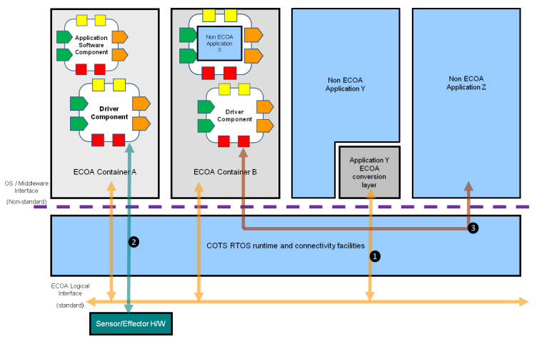
A key objective is to be able to deploy ECOA Application Software Components on legacy vehicle platforms and to be able to integrate non-ECOA software and hardware with an ECOA System.
The implementation of a legacy software application may not be consistent with the Inversion-of-Control principle. Legacy applications are likely to be closely coupled to an existing platform including operating system interfaces. Such applications may control their own execution (e.g. scheduling, threading), unlike an ECOA Application Software Component. This may imply the inability to effectively decompose application software into cohesive Modules, and may necessitate bespoke modifications. A legacy system that consists of hardware and / or software can be integrated with an ECOA System using a number of methods including the following:
- Wrapping or re-engineering as an ECOA Module that implements the necessary Inversion-of-Control behaviour (Application X).
- Development of an ECOA Conversion Layer for a non-ECOA application to provide an interface compliant with the ECOA Logical Interface (ECOA Conversion layer embedded in Application Y).
- Or, if the legacy application is (figuratively or literally) a "black box" then a dedicated Driver Component would be required (Component of B connected to Application Z).
THE ECOA BUSINESS MODEL APPROACH
To support modular system design and implementation with reusable components, a variation of the traditional business model is required. Consequently, within the ECOA collaboration programme, attention has been given to establishing a sustainable ECOA business model, which supports and is part of the comprehensive business model .
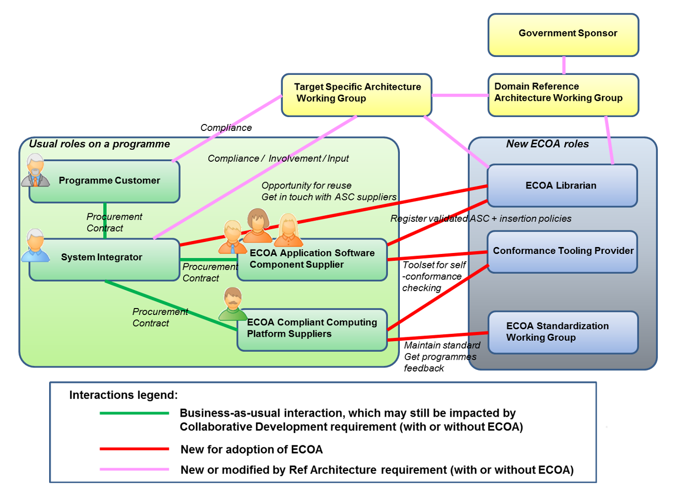
The ECOA business model has identified new business actors and their responsibilities, as well as highlighting specific activities related to modular/reusable systems that are being developed collaboratively. These activities integrate well with current business and system development practices.
ECOA TECHNOLOGY DEMONSTRATION
At each major milestone of the ECOA programme a technical demonstration of the main architectural features has been performed. The demonstration has become progressively more complex with partner companies in both France and the United Kingdom developing software components in accordance with ECOA principles. These components interact to provide a simulated surveillance capability similar to those used for crime prevention, crop management and related applications in order to demonstrate and test the key ECOA features.
The team have successfully demonstrated the portability of software components between a number of United Kingdom and French computing platforms. The same software components were used without modification on each target platform, to provide the simulated surveillance capability demonstrating the high level of software component level portability that ECOA delivers.
The ECOA demonstration has been designed to test the key features of the architecture specification. To achieve this a simulation has been developed of an unmanned aerial vehicle that is flown along a pre-determined route. The vehicle is tasked with capturing ground imagery at specified locations along the route.
A small sample from the demonstration is shown above.
ECOA TOOLSETS
ECOA related engineering toolset requirements for a particular project are dependent on a number of factors:
- The Systems Engineering processes adopted for the design phase
- The stakeholder role in the project - Systems Integrator / Software supplier etc
- Size and complexity of the system to be developed
- The number of stakeholders
- Protection of stakeholder intellectual property
ECOA has been designed to provide maximum implementation flexibility for an exploitation programme. This flexibility ensures ECOA design methodologies can be easily integrated with existing systems engineering processes without radically changing the design process. As a result systems integrators are able to retain their customised design processes and can develop bespoke toolsets, or additional design tool profiles, to achieve this.
ECOA provides a formal architecture specification and therefore it is envisaged that there will be an increased level of standardisation in ECOA related toolsets that support the implementation phase. Strategies for ensuring wide availability of ECOA tools such as systems analysis tools, code generators and compliance tools are being developed.
The following pages provide information on the design and implementation phase toolsets required for a major platform exploitation and the potential toolset development providers.
ECOA TOOLSETS - DESIGN PHASE POTENTIAL TOOLSETS
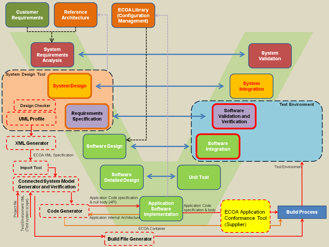
ECOA design and implementation phase tools have been prototyped and demonstrated. These have been used successfully to support demonstration activities. It is expected that toolset providers could commercialize production level toolsets for the industry based on the toolset map illustrated.
ECOA TECHNICAL TRAINING
A number of tutorials and examples have been developed that provide a basic appreciation of ECOA key features. These examples provide individuals with the information required to develop simple ECOA systems. These examples can be used, in conjunction with the project level documentation, to develop a more in-depth understanding of ECOA.
For more information please refer to the Official ECOA Website - Tutorials